Description
2-Channel RS485 Repeater with Photoelectric Isolation and Wide Voltage Support
Feature:
1. Complete Isolation of Communication: The repeater module adopts an industrial-grade design, providing complete communication isolation, stable and reliable performance, and a transmission rate of up to 300Kbps.
2. Isolated Power Module: The repeater module includes a built-in high-performance DC-DC isolated power module to achieve electrical isolation between ports.
3. 2-Channel Output: The repeater module supports 2-channel output for multi-device communication, allowing up to 256 nodes per channel with extended transmission distance.
4. Automatic Control Technology: The 2-channel repeater features automatic data flow control technology that automatically detects and manages data transmission direction.
5. Multiple Protection Measures: The 2-channel repeater offers ±15kV ESD protection, 600W dual TVS protection, and 2.5kV communication isolation.
6. Wide Power Supply Range: The 2-channel repeater supports a wide input voltage range of 9–36V DC with reverse connection protection and is compatible with standard DIN rail mounting.
Specification:
Item Type: Repeater Module
Material: PP
Operating Voltage:
- Typical Value: DC 9–36V
- Limit Value: DC 40V
Power Rating:
- Typical: 0.36W (9V/35mA; 12V/27mA; 24V/15mA)
- Limit Value: 0.5W
Operating Environment:
- Typical: Temperature: -30°C to 80°C, Humidity: >95% RH
- Limit Value: Temperature: -40°C to 85°C
Isolation Voltage:
- Typical: 2000V
- Limit Value: 2500V
Interface Protection:
- Typical: 600W Thunder Surge
- Limit: 600W
Load Capacity:
- Typical: 1–128 Nodes
- Limit: 256 Nodes
Communication Distance:
- Typical: 0–1500m
- Limit: 2000m
Communication Speed:
- Typical: 300bps–115.2Kbps
- Limit Value: 300Kbps
Dimensions: Approx. 100 x 54 x 32mm / 3.9 x 2.1 x 1.3in
Status Indicators:
- Power Indicator: Red, stays on when powered
- Data Indicator: Green, blinks when data is transmitted on the bus
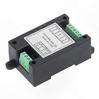
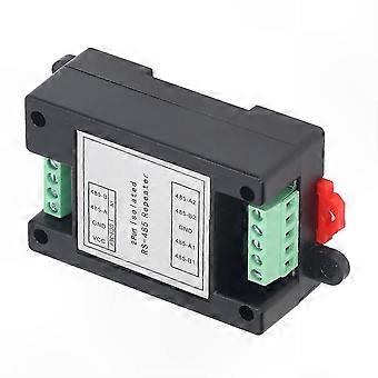
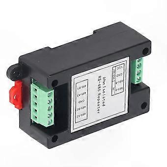
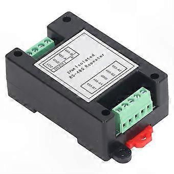
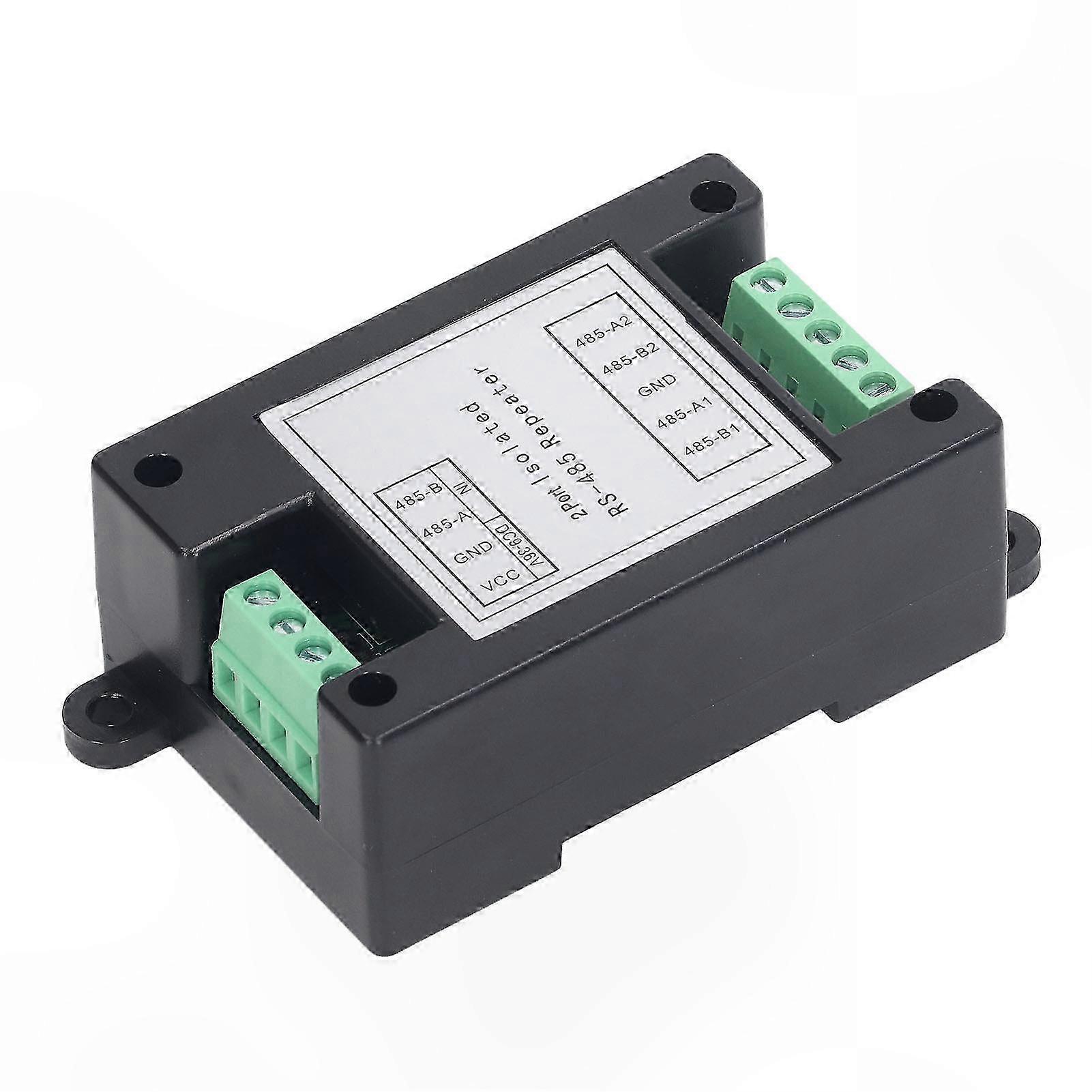
Terminal Interface Definition:
- VCC: Power supply interface (DC 9–36V)
- GND: Negative power supply terminal
- 485 A: RS485 signal input or output positive terminal
- 485 B: RS485 signal input or output negative terminal
- 485 A2: Second RS485 signal input or output positive
- 485 B2: Second RS485 signal input or output negative
- GND: Isolated RS485 terminal ground, can be connected to earth or shielding wire
- 485 A1: First RS485 signal input or output positive
- 485 B1: First RS485 signal input or output negative
How to Use:
A. RS485 Wiring Notes:
1. Use shielded twisted pair cable for RS485 communication lines, preferably with spare strands; total length should not exceed 1500 meters.
2. Keep wiring away from high-voltage power lines; avoid parallel routing or bundling with power cables.
3. RS485 bus must use a daisy-chain (hand-in-hand) topology; star or branched connections are not recommended.
4. Use an RS485 repeater when connecting more than 30 controllers or when cable length exceeds 500 meters.
5. Ensure AC-powered equipment and chassis are properly grounded.
6. Connect the GND of all RS485 devices using a shielded wire.
B. RS485 Bus Cable Selection:
- Use 2-core shielded twisted pair cable
- Copper conductor, wire diameter 0.5–0.75 mm²
- Impedance: 38–88 ohms/km
- Capacitance: 30–50 nF/km
- Twist pitch: 20 mm for 2-core shielded twisted pair (for runs under 500 meters, standards may be relaxed but must remain twisted pair)
C. Bus Requirements:
- A bus consists of two or more physically connected devices.
- Maximum of 256 devices allowed on the bus without repeaters; maximum bus length is 1500 meters.
- The bus must not have branches. If branches are unavoidable:
1. Branch length must not exceed 10 meters; total bus length must not exceed 800 meters; maximum of 50 devices per branch.
2. Keep signal lines away from interference sources; route signal lines through low-interference pathways. Avoid running parallel to high-power lines (e.g., 220V) or RF signal lines (e.g., CATV). Maintain separation of at least 0.5 meters if parallel routing is necessary.
3. All wire joints must be securely soldered or crimped and sealed against moisture using waterproof tape or epoxy resin.
D. Signal Common Ground:
1. All devices on the same network segment must share a common signal ground to prevent common-mode interference.
2. For centralized power supply systems, connect the negative DC terminals of all devices (including those with independent power) to form a common signal ground, which serves as the DC power ground.
3. For systems with independent power supplies, connect the ground (black wire) pins of all bus devices to establish a common reference.
-
Fruugo ID:
411034738-869820924
-
EAN:
1101063986986
Product Safety Information
Please see the product safety information specific to this product outlined below
The following information is provided by the independent third-party retailer selling this product.
Safety Warnings:
Please use according to the instructions or product details!
Delivery & Returns
Dispatched within 24 hours
Shipping from China.
We do our best to ensure that the products that you order are delivered to you in full and according to your specifications. However, should you receive an incomplete order, or items different from the ones you ordered, or there is some other reason why you are not satisfied with the order, you may return the order, or any products included in the order, and receive a full refund for the items. View full return policy